Many Suzuki SJ-413s built from its introduction in 1986 to the year1989 were equipped with a Hitachi Carburetor. While being the heart of the trucks fuel efficiency, it tended to get a bit cranky as the years and miles passed. This crankiness was mostly caused by the many vacuum lines, air valves, switches and sensors that made that fuel efficiency possible. And when something broke loose, a tinkering owner often made the problem worse by tearing down things and not putting those things back not exactly as they were.
A mighty wad of hose, plastic and metal is the Hitachi Carburetor! Complex beyond the abilities of the Mortal Shade-Tree Mechanic!
Until now.
Here, now (and at long last) is a pictoral with some helpful words that you can use to untangle what either normal wear-and-tear or the acts of someone (certainly not you!) has done to your poor Hitachi to make it run like -- well run terribly.
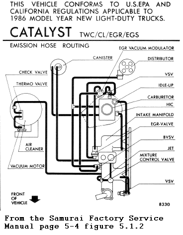
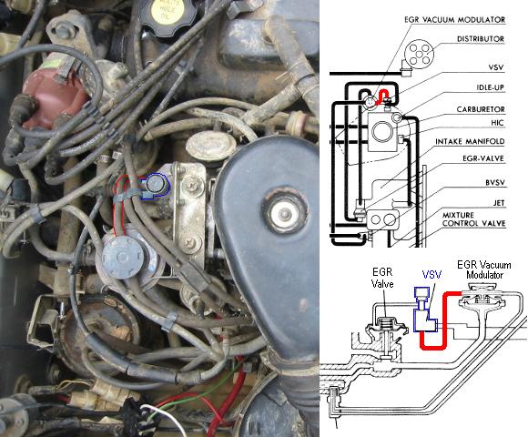
This is what that sticker inside your hood (or bonnet in some parts of the world) actually looked like when new. It may look complicated, but if you compare the drawing to the layout of the engine and carburetor, you can use some of the geography under the hood to spot where hoses go and what they are connected to.
The easiest ones to spot are connected to the air cleaner, EGR valve, the distributor, the VSV assembly by the thermostat/radiator hose outlet, the BVSV gadget just near the thermostat on the side of the intake manifold and the EGR Vacuum Modulator/VSV assembly at the other end of the intake manifold next to the carburetor. The tough ones are usually the untouched ones. Those hoses connect directly to the carburetor body or the intake manifold itself.
Here is one that usually gets damaged by heat and careless disassembly:
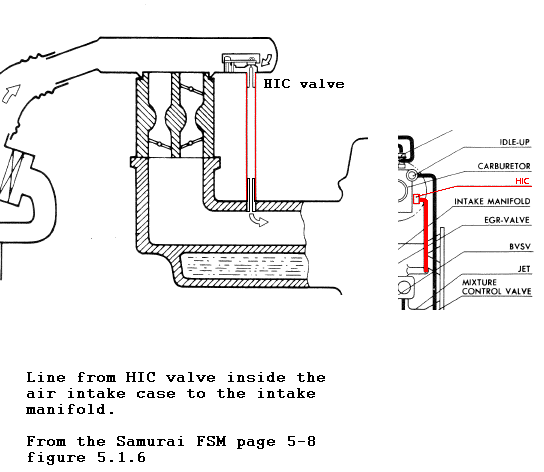
The vacuum line between the HIC valve under (!) the air intake case and the intake manifold runs vertically and does not have very much slack in it. If the air intake case is not carefully removed, the manifold end can be pulled off or broken. This end of the hose can easily become brittle from long exposure to heat. It is also easy to overlook.
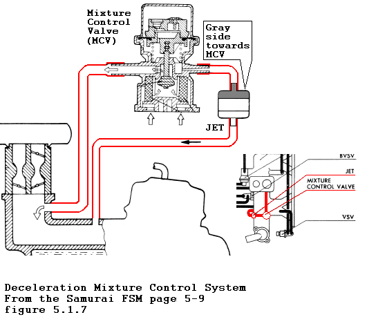
The Mixture control valve is mounted towards the front of the engine. Note that in the hood schematic, both vacuum lines connect to the intake manifold one on the face of the manifold directly under the carburetor and another though a round plastic gadget called a JET. That gadget must be mounted with the gray side facing the Mixture Control Valve (MCV) or things will not work correctly!
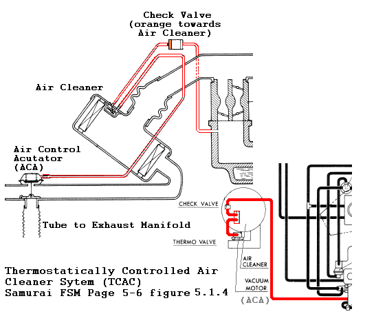
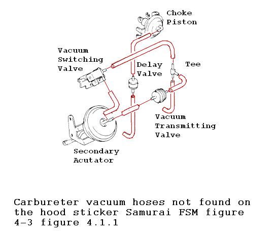
Another tricky section is the vacuum circuit that runs though the air filter area to a valve mechanism (the Air Control Acutator or ACA) that pulls heated air off the exhaust manifold (do you still have that accordion tube on you exhaust manifold shroud?). The line comes from the side of the carburetor facing the fender (see the hood schematic) through a one-way valve to a sensor inside the air cleaner and then on to the ACA. The tricky part is the one-way check valve.Note in the picture above that the Orange side of the valve faces the air cleaner. If it is installed backwards, the ACA will never open.
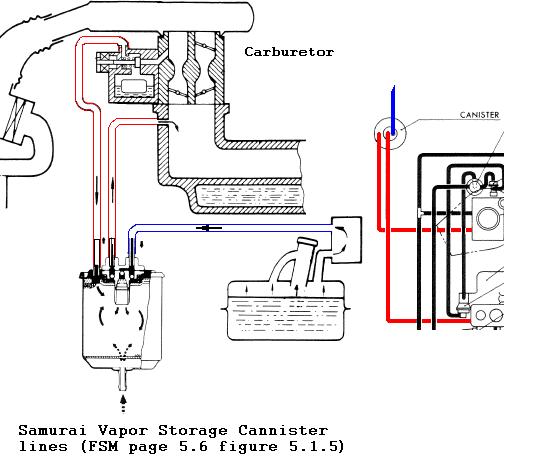
The Vapor Storage Canister circuit is easy to trace at the canister end.There are actually three hoses that connect to the canister.Two of them are vacuum lines pair that are on one side of the canister.
The vacuum line closest to the center of the canister runs to the intake manifold on the fender side near the front as pictured in the hood schematic and in the photo above.
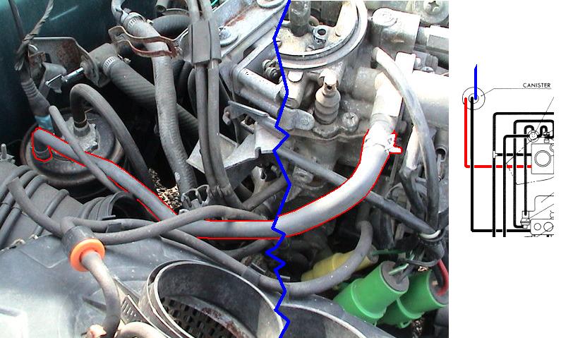
The other vacuum line runs to the carburetor itself as seen in the picture above.
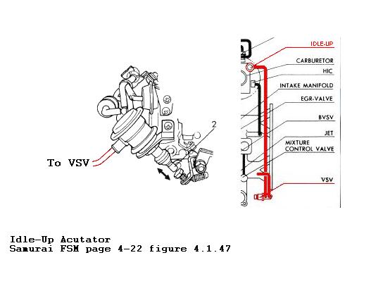
Here is a photo (courtesy of 87zuke) of the hoses attached to the VSV.The top hose connects to a fitting on top of the intake manifold while the bottom hose snakes back towards the carburetor and the Idle-up unit
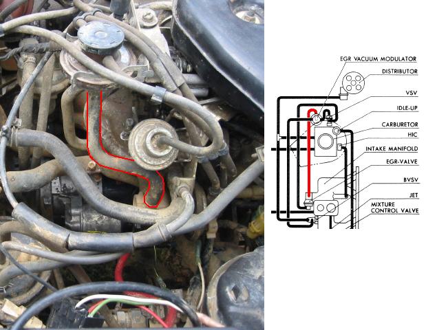
Here are pictures of several vacuum line connections that are not easy to figure out from the pictures and schematics above:
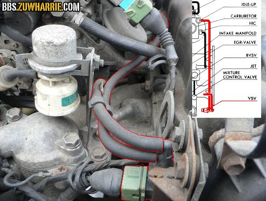
The vacuum line that has a tee in it is pictured below. The leg of the tee runs to a connection on the manifold just below the carburetor next to the vacuum line that runs to the vapor canister.The top part of the tee runs to the distributor to provide vacuum advance while the bottom part of the tee connects to the outboard connection of the VBSV unit, outlined in blue.
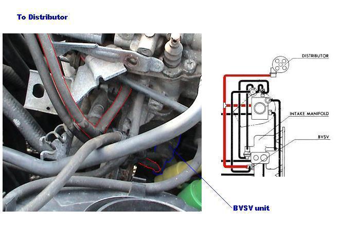
The other line from the BVSV unit goes back to the EGR Vacuum Modulator, pictured below.
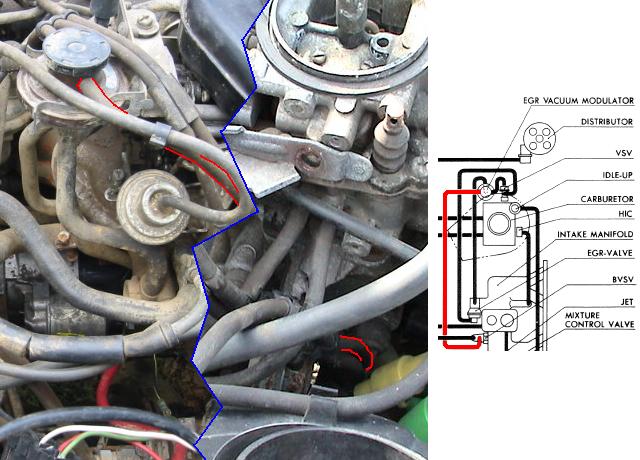
A large hose goes from the bottom of the EGR Vacuum Modulator to the EGR Valve itself:
A line comes out of the opposite side of the EGR Vacuum Modulator and to the bottom of the VSV valve
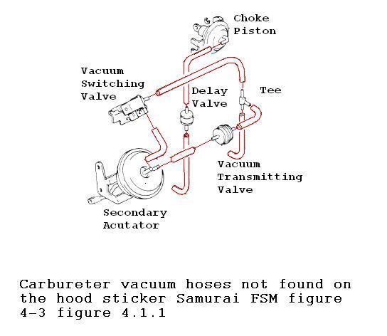
Finally, there is this subsystem of vacuum hoses on the inboard side of the carburetor next to the head.
That should be all of them.